Special features & accessories for central unit RZ-24
Kenmerken
- Besides the standard functions, the central unit RZ-24 offers many more possibilities
- These especial functions can be realized by using additional components
- Among these are the rechargeable battery buffering, a time relay, the use of the RZ-24 as a signal control, additional signal contacts, etc.
- Further options available upon request
- In some cases, the use of additional components may require the version with the larger casing
- We will gladly assist you with choosing the additional components for the RZ-24

Productinformatie
Central RZ-24 as signal control
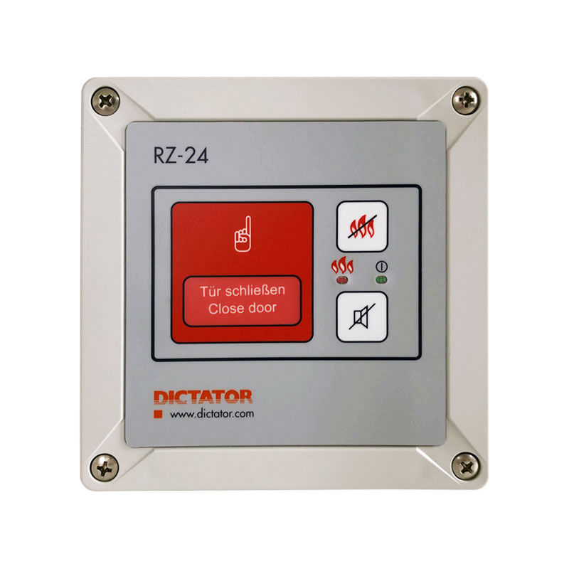 The RZ-24 central unit also allows to control a siren and a signal light during the closing of a fire door.
Acoustic and optical warning signals can be especially used on power-operated doors for which the demands of the standard EN 12604 have to be observed.
Functions
- The signallers are activated the moment when the power supply of the hold-open system is cut off and the door starts to close
- There are 3 ways of switching off the signallers after the door is closed:
- Installation of a time relay circuit board (part no. 040562), on which the time until switching off can be set (see ‘Time relay circuit board’ tab)
- Installation of an additional limit switch in the closed position
- By hand via the RESET button on the cover of the RZ-24
- Should the signaller also be able to function in the event of a power failure, the central unit RZ-24 in the large casing (art. no. 040554) has to be used together with the emergency power supply (art. no. 040555). The emergency power supply is installed in the casing of the RZ-24 and simply plugged in the main circuit board
- The central unit RZ-24 is also available as ‘signal control’ completely pre-assembled with timer relay and emergency power suply (article no. 040561)
Signaller

General information
- For use with the central unit RZ-24, using the signaler (article no. 700171) is recommended
- Includes both a siren and a flashing light
- Acoustic and optical warning signals are used especially for power-operated doors where the demands of the EN 12604 must be observed
- Adjustable volume
- If necessary, the siren can also be completely deactivated, e.g. when a signaller is mounted on each side of the door to make sure the warning light is seen from both sides – in this case it is normally enough if only one siren sounds
- Extremely low power consumption
Technical data of the signaler
| Voltage | 24 VDC |
| Power consumption | aprox. 26 mA when siren activated, 6 mA when siren desactivated |
| Volume | about 100 dBA, can be reduced by the integrated potentiometer |
| Flashing frequency | 1 Hz |
| Colour | red |
| IP rating | IP 65 |
| Dimensions Ø x h | 97.5 x 104 mm |
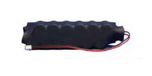
Emergency power supply for RZ-24
General information
- The emergency power supply allows for a short time to buffer the hold-open system during a power cut.
- The length of this hold-up time depends mainly on the power consumption of the connected components.
- As energy storage devices, capacitors are used instead of accumulators. They are less sensitive to temperature influences, have shorter charging times and a much longer service life.
- When using this emergency power supply, the RZ-24 central unit has to be in the large casing. In this casing is enough room for placing the battery pack.
- Its connection cable is simply plugged in the provided jack on the printed circuit board of the RZ-24.
- During normal operation the battery pack recharges automatically.
- Charging time: about 1 hour for 80 % of the capacity, about 4 hours for 100 % of the capacity.
Hold-up time
- The battery pack has an output of 0.022 Ah
- All of the following values for the length of the hold-up time are only for orientation!
| Load at U-Nominal 24 VDC | Hold-up time |
|---|---|
| 70 mA + 30 mA own consumption = 100 mA (0.1 A) | 10,91 minutes |
| 140 mA + 30 mA own consumption = 170 mA (0.17 A) | 6,42 minutes |
| 280 mA + 30 mA own consumption = 310 mA (0.31 A) | 3,52 minutes |
Notes:
- The own consumption of the RZ-24 is 30 mA
- The fire alarm loop of the RZ-24 sets off at a tension of about 16 VDC
- The hold-up times depend on the charging state of the emergency power supply and the ambient temperature
Simplified calculation formula:
Hold-up time in seconds = 80/load [A]
Example:
Hold-open system with RZ-24 and 4 smoke detectors RM 4000 & 1 electromagnet EM GD 70:
- RZ-24: own consumption 0.03 A
- 4 x RM 4000: 4 x 95 μA = 380 μA = 0.38 mA = 0.00038 A
- Electromagnet EM GD 70 = 71 mA = 0.071 A
Total consumption: 0.101 A
Hold-up time = 80/0.101 A = 792 seconds (about 13 minutes)
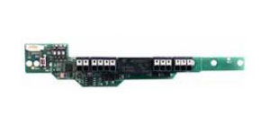
Time relay circuit board
 General information
- The time relay circuit board is incorporated into the RZ-24 central unit
- Therefore, the RZ-24 with the large casing must be used together with the time relay circuit board
- Thanks to the time relay circuit board, different time-controlled functions can be implemented, such as:
-
-
- Switching off the signalling after a certain time (e.g. when using the RZ-24 as signal control)
- Signalling that the door will close shortly (e.g. mandatory in Austria for doors in underground car parks) – release delay
-
-
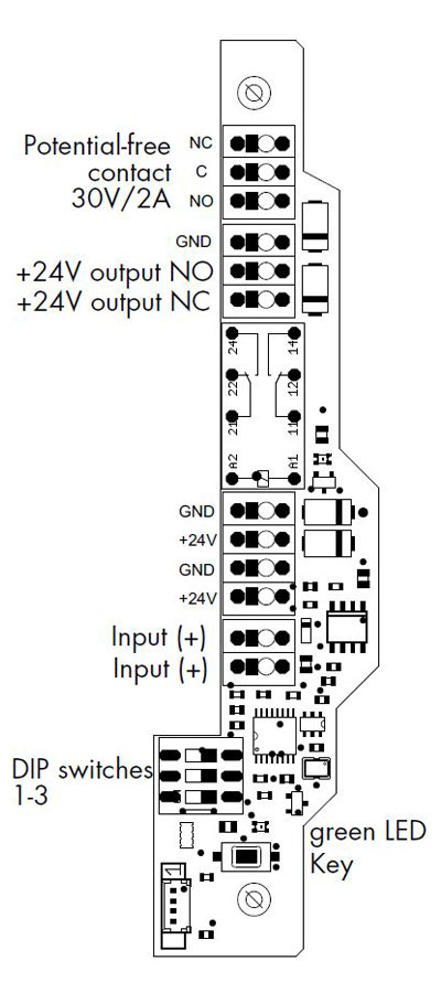
- The desired function and time range are set using 3 DIP-switches and a programming button
- The successful input is indicated by a green LED
Technical data
| Relay | 24 VDC, 25 mA |
|---|---|
| 1 changeover contact | 2 A, 30 VDC |
| 1 output | 24 VDC, max. 2 A, with potential |
| Selectable functions | on-delay, power-off delay, interval with signal on, interval with signal off, symmetrical flasher (starting pulse on), symmetrical flasher (starting pulse off), pulse shaper |
| Adjustable periods | hours : minutes: max. 96 h : 59 min minutes : seconds: max. 59 min : 59 s 100 milliseconds : 10 milliseconds: max. 10000 ms :1000 ms |
| Dimensions | 112 x 27 mm |
Additional circuit board for the automatic reset of the RZ-24
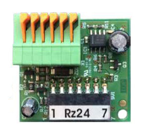
General information
After every manual release or fire alarm the complete hold-open system has to be reset. Two steps are necessary:
- Resetting the fire detectors by pressing the hand release switch
- Resetting the complete hold-open system by pressing the RESET key
Only when these two steps have been performed, the electromagnets are supplied with current again and the doors can be locked in the open position. If the doors are used by many different people who are not familiar with the details of the hold-open system, the additional circuit board for the automatic reset of the RZ-24 should be used. Furthermore, the RZ-24 control panel is not always directly accessible. However, since the RESET button is located on the casing of the RZ-24, the additional board not only eases the reset, but also saves time. The circuit board is simply plugged on the main circuit board of the RZ-24, for which the small casing is enough.
Functioning
- After a power failure, releasing the system by a hand switch or removing and inserting again a fire detector: automatic, RESET of the whole hold-open system.
- After a fire alarm triggered by a fire detector: First is required a manual reset of the detectors by the hand release switch. Then the RESET of the central unit is performed automatically. As the RZ-24 central unit is not always within reach, the RESET key, however, is on its casing, the additional circuit board not only makes the reset easier but also saves time.
- The reset command is automatically carried out every 8 seconds.
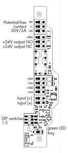
Relay circuit board with 1 additional contact
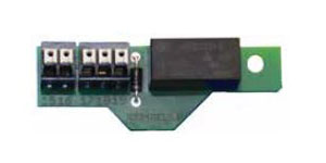
General information
- By default the RZ-24 central unit has a potential-free contact for passing on the tripping. Should this not be sufficient, an additional circuit board with a relay contact can be refitted
- Models with 2 or 4 contacts also available on demand
- Generally we recommend to choose the RZ-24 with the large casing when installing this additional circuit board
Technical data
- 1 relay 24 VDC
- 1 potential-free changeover contact 2A
- Dimensions: 55 x 19 mm
Bestelinformatie
| Omschrijving | Artikelnr. |
|---|---|
| Zusatzplatine zur automatischen Rückstellung der Zentrale RZ-24 nach Stromausfall und Brandalarm | 040556 |
| Relaisplatine zu Zentrale RZ-24 mit 1 Relaiskontakt, potentialfreier Wechselkontakt 2 A, 30 VDC | 040559 |
| Zeitrelaisplatine zum Einbau in die Zentrale RZ-24 mit großem Gehäuse, Relais 24 VDC/25 mA, 1 Wechslerkontakt 2A/30 VDC, 1 Ausgang potentialbehaftet 24 VDC/max. 2 A (großes Gehäuse) | 040562 |
| Audiovisueller Signalgeber bestehend aus roter LED Blitzleuchte mit separat schaltbarer Warnsirene, IP65 | 700171 |
| Energieversorgungseinheit mit integrierter Auslösevorrichtung RZ-24, 0,9 A, IP 64, 202x152x90 mm (großes Gehäuse), Notstromversorgung und Zeitrelaisplatine als Signalsteuerung für Schiebetore | 040561 |
Downloads
| File name | Type | Date of modification |
|---|---|---|
| Catalog Central units for hold-open systems | 2023/04/06 |