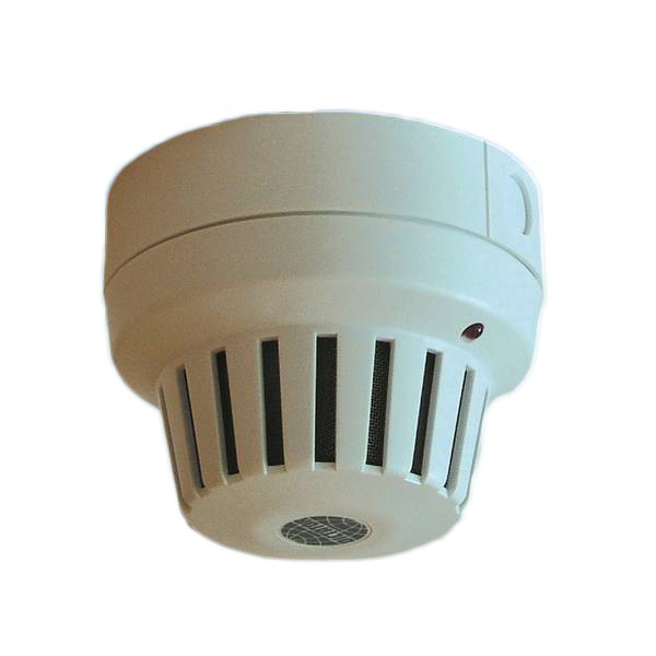
Heat detector WM 2000 (Replacement)
 with Base and Tripping Device for Hold-Open Systems
The WM 2000 heat detectors have been used in hold-open systems of fire protection closures, except for doors in escape routes. Here heat detectors are never allowed.
The WM 2000 is among others included in the following approvals: Z-6.5-1903, Z-6.5-1707.
To ensure the correct functioning of the hold-open system, the DICTATOR smoke and heat detectors have to be replaced after a maximum of 8 years of operational life. In Germany the DIN 14677 regulates the replacement obligation of fire detectors in hold-open systems.
Since July 2019, this heat detector may no longer be manufactured in Germany due to the valid regulations of the Institut für Bautechnik. If a WM 2000 is used in an existing hold-open system from DICTATOR and must now be replaced, a completely new hold-open system RZ-24 with RM/WM 4000 in accordance with the current regulations must be installed.
- When the hold-open system is replaced with the currently approved hold-open system RZ-24, all smoke and heat detectors must be replaced.
- The existing power supply unit is omitted and replaced by the RZ-24 control unit.
- The hold-open device (usually a magnet) is connected directly to the control unit.
- Possible changes to the wiring or the use of existing cables on site must be checked on the basis of the situation on site.
- Please refer to the current general type approval for information on whether it is necessary to replace the hold-open device (magnet, door closer, drive).
| Voltage | 24 VDC, +15 %, -10 % |
| Power consumption | 15 mA |
| Alarm temperature | 60 °C |
| Protection | IP 42 |
| Casing | white plastic casing |
| Switching capacity | 24 V DC / 1.0 A |
| Temperature class | A1R |
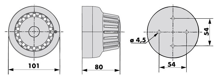 | All dimensions in mm |
 When using the WM 2000 heat detector on fire protection doors it is imperative to observe the guidelines for hold-open systems set by the Institute of Building Engineering in Berlin.
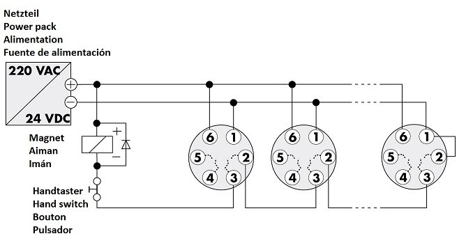
First of all the socket is fixed and connected electrically.
The WM 2000 heat detectors operate with 24 VDC which is supplied at the terminals 1 and 6 (see adjoining wiring diagram). They are not equipped with a mains transformer.
Terminals 2 and 3: potential-free relay contact (contact “a”). It opens in event of alarm or power failure.
Terminals 4 and 5: second potential-free relay contact (contact “b”).
While contact “a” always opens, contact “b” can either open or close, depending on the heat detector model.
– Model 040511: “b” opens upon alarm.
– Model 040512: “b” closes upon alarm.
If several heat detectors are wired in series, you need to bridge the terminals 1 and 2 of the last heat detector.
Insert the heat detector into the socket so that the light diode coincides with the mark in the socket. Then turn it to the right for about 1.5 cm until it snaps in. It is now ready for operation.
The prescribed hand switch can be mounted anywhere on the feed line which is connected to the electromagnet or the door closer with integrated hold-open.
IMPORTANT:
– Remove the dust protection bag only when the installation is terminated.
– For the cable entry the included membrane grommet has to be used.
– Protect the heat detector from dust, colour mist and moisture to prevent malfunction.
| File Name | Type | Date of modification |
|---|---|---|
| Catalog: Heat Detector WM 2000 | 2021/01/27 | |
| Approval for Smoke Detectors | 2015/02/11 |